Tekla Structures Concrete Modelling: A Disciplined Workflow from Model
to Drawing
# Tekla Structures Concrete Modelling: A Disciplined Workflow from Model to Drawing
In structural BIM, Tekla Structures concrete modelling is about more than creating accurate 3D geometry. Tekla Structures acts as an information engine, bringing together the data behind every part of the model. Every element, property and relationship contributes to the information used throughout the project, from construction documentation and drawings to quantity take-offs and delivery.
BuildingPoint Australia·Tekla Structures·9 min read
A common pitfall is the “visual trap”: assuming that because a model
looks correct in 3D, it is technically sound. In reality, a model can
look perfect while producing incorrect quantities, missing
reinforcement in reports, or broken drawing links, and by the time
that surfaces, it means costly rework and site disruption.
To avoid this, you must move beyond “visual modelling” and treat Tekla
as a relational database, where geometry is only a byproduct of
correctly managed object relationships. The core philosophy:
The core workflow
Set up→
Model→
Attach→
Inquire→
Verify→
Calculate→
Check→
Report/Drawings
Why a Disciplined Workflow Matters
A small error in the modelling phase doesn’t stay small, it can
cascade through the entire project lifecycle:
Inaccurate material take-offs and quantities
Incorrect Cast Unit or Pour Unit information
Missing embeds and items in production reports
Numbering conflicts and broken production drawings
BIM export and coordination failures
The Model Hierarchy: Phase, Cast Unit, and Pour Unit
Before placing a single column, you need to understand how Tekla
organises data. These three levels are frequently confused, but they
serve distinct purposes:
The project-management layer
Phase
Organises the model into logical sections (e.g., Zone A, Stage 1)
and manages contractual or release boundaries. Reserved for
high-level structure, not manufacturing detail.
The manufacturing layer
Cast Unit
Represents everything manufactured as a single piece: the main
concrete part, secondary parts, embeds, and reinforcement.
Critical for Precast.
The construction layer
Pour Unit
Defines what concrete and associated objects are poured together
on-site. Dynamic — built from “Calculate Pour Units” logic.
Critical for Cast-in-Place (CIP).
Phase Setup: Establish the Foundation First
Agree on the Phase structure before extensive modelling begins.
A consistent structure lets you filter the model, isolate work
areas, and coordinate multiple teams.
Concrete Geometry and the “Solid Check” Protocol
Geometry is the foundation everything else depends on. Ensure
correct profiles, dimensions, and openings — and avoid duplicate
concrete — before adding detail.
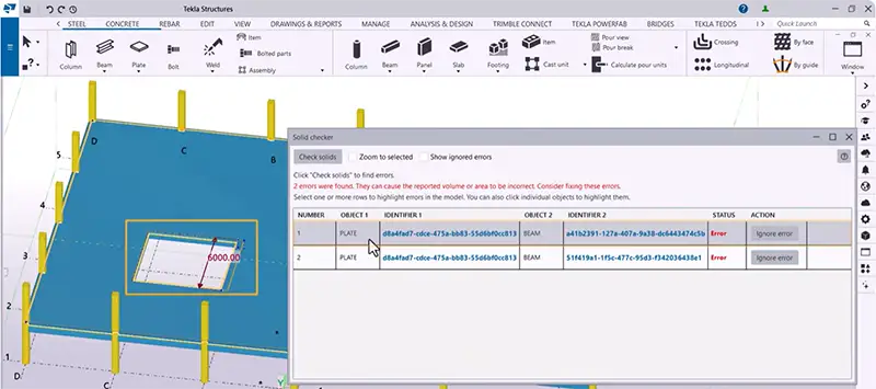
A concrete object that looks correct on screen is a good start,
but ensuring it is a valid solid help maintain accurate reports,
drawings, quantities, and weights. By avoiding issues such as
invalid profiles, overlapping cuts, or self-intersections, Tekla
can reliably calculate volumes and generate dependable downstream
documentation.
01Create the geometry.
02Run a Solid Check.
03Identify and correct errors immediately.
04Only then proceed to reinforcement.
Precast vs. Cast-in-Place: The Critical Fork in the Road
How you classify your concrete changes the entire downstream workflow:
Precast
Focuses on Cast Units and manufacturing orientation. The goal
is a production drawing for a single element.
Cast-in-Place
Focuses on Pour Phases and Pour Units. The goal is managing
the sequence of concrete delivery on-site.
The Precast Workflow: Master the Cast Unit
In Precast modelling, the Cast Unit is king. It represents everything
manufactured as one piece — the main concrete part, secondary parts,
embeds, and reinforcement.
The Main Part Rule
Every Cast Unit needs a designated Main Part, which carries
the primary metadata for the whole unit. If the Main Part
changes mid-project, you risk losing associated UDA data.
Attach, Associate, Inquire
Don’t assume an embed belongs to a panel just because it’s
touching it. Manually add it to the Cast Unit, then use
Inquire Cast Unit to verify the hierarchy.
Sub-assembly strategy
For complex elements (e.g., a double-tee with integrated plates
and lifting loops, or a wall with a cast-in corbel), model the
embed as a sub-assembly before adding it to the Cast Unit.
This keeps its own parts (bolts, plates) together in the BOM
and lets you manage it independently while it still rolls
up into the main Cast Unit.
Orientation and snapping — trowel face vs. bed face
For Precast, part orientation determines which face is the
trowel face and which is the bed face. Snap to the correct
start and end point when placing and orienting the part,
rather than eyeballing it in 3D and flipping the orientation.
Swapping trowel and bed faces could throw off rebar cover or
cuts on the exposed face, flip embed and lifting-anchor
positions and can put finish call-out (e.g., broom finish,
form finish) on the wrong side.
The Cast-in-Place Workflow: Pours and Breaks
For cast-in-place (CIP) projects, the focus shifts from manufacturing
individual concrete elements to planning how the concrete will be
poured on site. This means organising the model around Pour Phases
and Pour Breaks so that each pour reflects the intended construction
sequence and can be accurately reported, coordinated and documented:
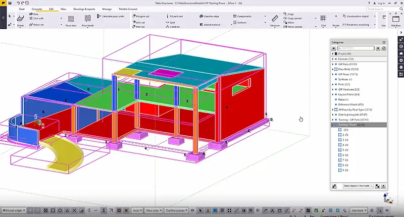
Pour Breaks
Must properly — and physically — divide the intended concrete.
When the break fully crosses the beam as intended, Tekla
Structures can correctly separate the pour and produce
reliable volume reports.
Calculate Pour Units
Run this regularly — treat it as a daily habit. It’s how Tekla
determines which reinforcement and embeds belong to a pour,
based on location.
QA Step
Switch to Pour View and visually confirm that what Tekla sees
as the “Pour” matches site construction intent. Color-coding
by Pour Number makes it easy to spot anything unassigned.
Reinforcement: Attachment Is Everything
Reinforcement is most effective when modelled after the concrete
geometry is stable. This maintains the correct relationship
between the reinforcement and concrete.
Verify attachment by asking:
Does the rebar appear in the Cast Unit / Pour Unit report?
If not, use Inquire to check its attachment status.
Does it appear in the Cast Unit drawing?
If you move the concrete, does the rebar move with it?
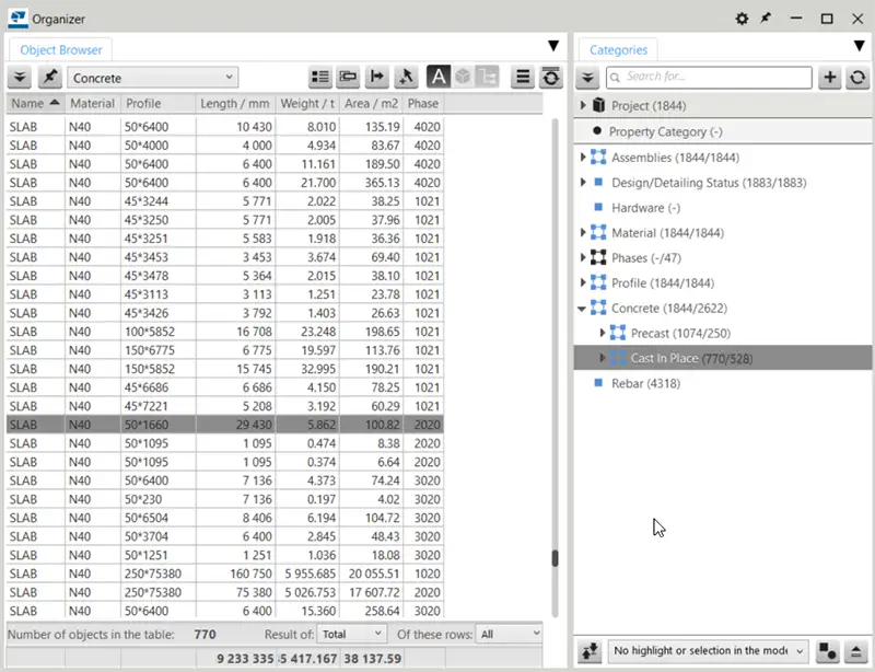
The QA Gate: Using the Organizer as Your Central Audit Tool
The exact properties and filters available will depend on how your
Tekla model and project environment are configured. The goal is not
simply to create a list of objects, but to make potential modelling
problems visible before they reach numbering, drawings, or reports.
Reports, Drawings, and Numbering: The Final Truth
Reports and drawings don’t fix the model; they read it. Both are
generated directly from the model’s object relationships, so if
your quantities are wrong or a drawing is missing content, the
fix is in the modelling relationships — not the report editor
or the drawing itself.
Drawings
Cast Unit and Pour Unit drawings inherit their content straight
from the model hierarchy. If an embed or bar isn’t correctly
attached to its Cast Unit or Pour Unit, it will not appear on
the corresponding drawing.
Numbering
Run numbering only after significant changes are verified —
and number by Phase or Selection rather than the whole model,
to avoid “numbering ripple effects,” where a change in one
zone accidentally renumbers another (and forces drawings to
be reissued unnecessarily).
Verification
Before issuing a report or drawing, Inquire the Cast Unit/Pour
Unit one last time to confirm all items, embeds, and bars
are included.
Troubleshooting Common Disruptions
Problem
Solution
Geometry looks right but Solid Check fails, or quantities
are wrong.
Look for overlapping cuts, invalid profiles, or duplicate
geometry.
Embeds are missing from production reports or drawings.
Check the Cast Unit hierarchy — the item was likely
attached to the part instead of the Cast Unit. Standardize
the “Attach to Cast Unit” command across the team.
Quantities are doubling.
Check for duplicate geometry or overlapping Pour Phases.
Incorrect Pour contents.
Check Pour Breaks and re-run Calculate Pour Units.
Numbering keeps changing for identical parts.
Look for subtle geometry differences (even ~0.5 mm) or
differing UDAs; use Compare Parts and reset UDAs.
Reports show “0” weight for a part, or drawings show
incorrect dimensions.
Check for a failed Solid Check or incorrect material
density in the catalogue.
Model-sharing sync conflicts.
Two users are likely modifying the same Pour Unit or
numbering series simultaneously; assign specific Phases
to specific users.
The Master Workflow at a Glance
01
Project Setup (Phases, UDA, Grids, References, Base Point)
02
Concrete Geometry (Solid Check & Material)
03
Classification(Precast vs. CIP)
04
Structure (Cast Unit / Pour Management)
05
Detailing (Attach Items & Reinforcement)
06
Verification (Inquire & Calculate Pour Units)
07
QA Audit(Organizer)
08
Final Output (Numbering, Drawings & Reports)
Conclusion: Model Correctly, Report and Draw Confidently
Reliable modelling in Tekla Structures is a matter of discipline,
not luck. By following a structured workflow and adopting an
“Inquire Before You Issue” philosophy — checking that Tekla
understands your model, not just that it looks right — you
eliminate the uncertainty that leads to project disruption,
whether that shows up in a bad quantity report or a drawing
that’s missing an embed.
Before you sync your model or issue a report or drawing, ask:
01
Is the geometry solid? (Can Tekla calculate the math?)
02
Is the relationship logical? (Does every object have a parent Cast Unit or Pour Unit?)
03
Is the data reportable and drawable? (Are UDAs and numbering consistent across the series,
and does every object show up where it should on the drawing?)
Next Steps for Mastery
Refresh Your Skills
Check out the official Tekla e-Learning modules.
Back to Basics
Make sure your team has the fundamentals down before tackling
complex geometry.
Standardize
Define your project structure and UDA schemas before the first
column is placed.
Tech Support: If you are looking for Product Tech Support please do not use this form. Please visit our Support Page to contact us for support questions.